VFO for my shortwave receiver
When I decided to start building a shortwave receiver I had quite a few ideas on how to build a VFO, ideas such as using variable capacitors, varicap diodes and what I finally settled for, a DDS.
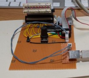
The reason I chose DDS was mostly because of frequency stability and the possibility to control it with a micro controller. In the image below you can see my first steps on the way with a AVR644 MCU and a LED display with a rotary encoder to set the frequency. This version did not contain the actual DDS chip since I had not yet received all parts.
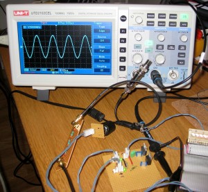
The next step on the way was to connect the DDS module to the CPU board and to a low pass filter. The results are in the image below. You can see a nice smooth sine wave at 3.6MHz.


