Category: Radio

VHF VFO

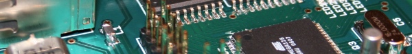
I bought a VFO kit by PA0KLT based on the SI570 from SDR-kits. It was very easy to assemble although I dislike winding the transformer. Here is an image of it completely soldered. I also bought an extra Si570 to use in future projects of my own.

PA0KLT VFO

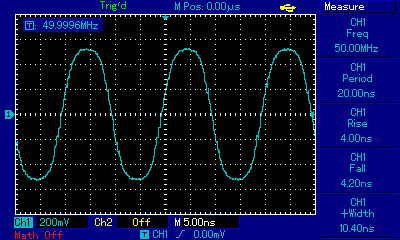
Connecting the display and buttons resulted in this mess, but it seems to work fine. It is possible to generate frequencies from somewhere around a few MHz to 280 MHz but since my oscilloscope only handles signals up to 100MHz I settled for 50MHz for the images here.

PA0KLT VFO wired up

And finally, the signal on my oscilloscope.


Superheterodyne Mixer

Here is my new mixer module. It is a superheterodyne receiver with a 4 pole 10MHz crystal filter. It uses a 10MHz crystal as BFO with the option to solder in a connector for an external MCU controlled BFO.

I have decided to use surface mounted components to avoid drilling since it is boring and creates lots of dust and noise. Sadly enough I could not find SMD versions of the SA612 at my local electronics supplier so I had to use the through hole mounted version. The connectors are also through hole mounted in order to get some mechanical stress relief.

Mixer module top

Component side of the mixer module. The RF mixer is on the left with RF in and LO connector. The right side is the IF mixer.

Mixer module bottom

On the solder side we can see the crystal ladder filter and the BFO with a trim capacitor to tune the BFO. The other trim capacitor is used to tune the LC circuit at the RF input.


Ideas for a new mixer

To fix my problems with bad selectivity in my direct conversion mixer I am planning on building a superheterodyne mixer to replace the current mixer.

My current plans look something like this, use a SA612 as RF stage mixer to convert the incoming 7MHz signals to 10MHz. I do not think that mirror frequencies will be an issue since I have a low pass filter with cutoff frequency of about 9MHz before the mixer module.

The IF filter is a 4 pole crystal ladder filter. I have not yet calculated proper values fo the capacitors but somewhere around 20 to 150pF should work.

The AF mixer has both a crystal oscillator and a connector for an external beat frequency oscillator. I plan to start by using the crystal oscillator and then switch to using a DDS based oscillator which will give me the possibility to add IF-shift functionality.

You can find the schematics below

Superheterodyne Mixer


Boxing it up

Now it is time to mount everything inside a nice enclosure.

I have chosen an aluminium case as it will add some shielding to keep unwanted RF out. There is quite a bit of free space in the case but some of it will be used when I build the new superheterodyne mixer module.

Some pictures of the inside of the radio
Inside the radio 1

Inside the radio 2


RF Mixer

The mixer circuit I decided to start with in my receiver is a simple direct conversion mixer based on the popular SA612. It uses a LC resonant with a hand wound transformer and a trim capacitor to create a band pass filter at about 7MHz, the 40M band. The local oscillator uses a AD9835 chip on a breakout board from Sparkfun (the red pcb) connected via a low pass filter with cut off frequency at about 14MHz.

There is one problem with this approach though, it has very poor selectivity and basically everything you throw at it will get through. I plan to fix this problem by building a new mixer module with two mixers and a narrow crystal filter at about 10MHz as IF filter.

In the image below you can also see my power supply using linear voltage regulators to get 5V and 8V and the current CPU board with the display connected.

RF Mixer mk1


VFO for my shortwave receiver

When I decided to start building a shortwave receiver I had quite a few ideas on how to build a VFO, ideas such as using variable capacitors, varicap diodes and what I finally settled for, a DDS.

The reason I chose DDS was mostly because of frequency stability and the possibility to control it with a micro controller. In the image below you can see my first steps on the way with a AVR644 MCU and a LED display with a rotary encoder to set the frequency. This version did not contain the actual DDS chip since I had not yet received all parts.

Experimental CPU board for the VFO

The next step on the way was to connect the DDS module to the CPU board and to a low pass filter. The results are in the image below. You can see a nice smooth sine wave at 3.6MHz.

DDS connected to my oscilloscope