Author archives: Michael

RF Mixer

The mixer circuit I decided to start with in my receiver is a simple direct conversion mixer based on the popular SA612. It uses a LC resonant with a hand wound transformer and a trim capacitor to create a band pass filter at about 7MHz, the 40M band. The local oscillator uses a AD9835 chip on a breakout board from Sparkfun (the red pcb) connected via a low pass filter with cut off frequency at about 14MHz.

There is one problem with this approach though, it has very poor selectivity and basically everything you throw at it will get through. I plan to fix this problem by building a new mixer module with two mixers and a narrow crystal filter at about 10MHz as IF filter.

In the image below you can also see my power supply using linear voltage regulators to get 5V and 8V and the current CPU board with the display connected.

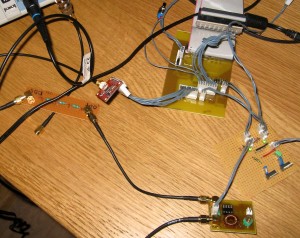
RF Mixer mk1


VFO for my shortwave receiver

When I decided to start building a shortwave receiver I had quite a few ideas on how to build a VFO, ideas such as using variable capacitors, varicap diodes and what I finally settled for, a DDS.

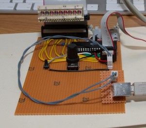
The reason I chose DDS was mostly because of frequency stability and the possibility to control it with a micro controller. In the image below you can see my first steps on the way with a AVR644 MCU and a LED display with a rotary encoder to set the frequency. This version did not contain the actual DDS chip since I had not yet received all parts.

Experimental CPU board for the VFO

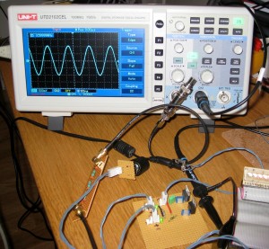
The next step on the way was to connect the DDS module to the CPU board and to a low pass filter. The results are in the image below. You can see a nice smooth sine wave at 3.6MHz.

DDS connected to my oscilloscope


Welcome to my electronics blog

Hi and welcome to my electronics blog.

Here I will document my various electronics projects and maybe some other things as well.

The first few posts will feature things I have built previously and gradually new projects will come.