My own STM32F1 dev board

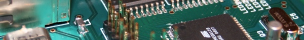
I decided to make my own STM32F1 development board to use for various projects. This is equipped with the STM32F103CBT6 MCU which has 128kB flash and 20kB ram. The board has a 19 pin JTAG header, 3.3V regulator, a few leds and headers for port a and b, 32 accessible IO pins. I have successfully driven a lcd and USB with this board and I am very happy how it turned out. The PCB is from OSHPark as my previous board. If I get more of these boards I will add silk screen with port numbers which I forgot in this revision. I have also cleaned the board a bit after this photo and added pin headers on the edges,

STM32F103 dev board

STM32F103 dev board

My next project is to build a more advanced dev board with a STMF4 cpu and an external SDRAM for more demanding applications.


Amplifier PCB

I got my boards from OSH Park after about two weeks. The boards look very well made and I can’t see any manufacturing errors on them. I’m sorry about the bad lightning on this photo. It’s hard with such a reflective surface.

PCB for my amplifier made by OSH Park

PCB for my amplifier made by OSH Park


Isolated distribution amplifier


To get more than one isolated output from my frequency standard I have decided to build this distribution amplifier. It uses one input amplifier and four output driver amplifiers connected to transformers to get ground isolated outputs.

I plan to design a board and then have it made by OSH Park.
Screen Shot 2015-10-06 at 14.45.08


Rubidium Frequency Standard

A new eBay purchase. A 10 MHz rubidium frequency standard fro mStanford Research Systems. It is of course used but it seems to be in good shape.

SRS rubidium frequency standard

A Stanford Research Systems rubidium frequency standard

I plan on putting this into a nice case with power supply and to build a distribution amplifier to get multiple isolated 10 MHz outputs.

Although it has a different model number it seems to be the same as the PRS10 10 MHz Rubidium Oscillator found on the SRS web site.


Rasberry Pi

I recently got a Raspberry Pi and I thought I would add a photo of it.

I have not yet built anything around it but it boots and I can connect to it using ssh. My plans are to connect it to a dot matrix display that I have lying around here and let it present the weather forecast or something similar.


VHF VFO

I bought a VFO kit by PA0KLT based on the SI570 from SDR-kits. It was very easy to assemble although I dislike winding the transformer. Here is an image of it completely soldered. I also bought an extra Si570 to use in future projects of my own.

PA0KLT VFO

Connecting the display and buttons resulted in this mess, but it seems to work fine. It is possible to generate frequencies from somewhere around a few MHz to 280 MHz but since my oscilloscope only handles signals up to 100MHz I settled for 50MHz for the images here.

PA0KLT VFO wired up

And finally, the signal on my oscilloscope.


Arduino

I bought an Arduino Uno recently to use when building prototypes. Using MCUs soldered to veroboard is nice, but it is not great for those projects where you just want to try something quickly. Thats where the Arduino comes in handy, now I can wire up something on a breadboard or solder a few things on a veroboard and connect the Arduino to control it.

A nice thing with the Arduino is that it uses an AVR MCU which means I can use my usual development tools such as AVR GCC when developing software and then transfer the code to a more permanent version later on.

Arduino Uno


Superheterodyne Mixer

Here is my new mixer module. It is a superheterodyne receiver with a 4 pole 10MHz crystal filter. It uses a 10MHz crystal as BFO with the option to solder in a connector for an external MCU controlled BFO.

I have decided to use surface mounted components to avoid drilling since it is boring and creates lots of dust and noise. Sadly enough I could not find SMD versions of the SA612 at my local electronics supplier so I had to use the through hole mounted version. The connectors are also through hole mounted in order to get some mechanical stress relief.

Mixer module top

Component side of the mixer module. The RF mixer is on the left with RF in and LO connector. The right side is the IF mixer.

Mixer module bottom

On the solder side we can see the crystal ladder filter and the BFO with a trim capacitor to tune the BFO. The other trim capacitor is used to tune the LC circuit at the RF input.


Ideas for a new mixer

To fix my problems with bad selectivity in my direct conversion mixer I am planning on building a superheterodyne mixer to replace the current mixer.

My current plans look something like this, use a SA612 as RF stage mixer to convert the incoming 7MHz signals to 10MHz. I do not think that mirror frequencies will be an issue since I have a low pass filter with cutoff frequency of about 9MHz before the mixer module.

The IF filter is a 4 pole crystal ladder filter. I have not yet calculated proper values fo the capacitors but somewhere around 20 to 150pF should work.

The AF mixer has both a crystal oscillator and a connector for an external beat frequency oscillator. I plan to start by using the crystal oscillator and then switch to using a DDS based oscillator which will give me the possibility to add IF-shift functionality.

You can find the schematics below

Superheterodyne Mixer


Boxing it up

Now it is time to mount everything inside a nice enclosure.

I have chosen an aluminium case as it will add some shielding to keep unwanted RF out. There is quite a bit of free space in the case but some of it will be used when I build the new superheterodyne mixer module.

Some pictures of the inside of the radio
Inside the radio 1

Inside the radio 2